Build Your Own JoyPhone
The purpose of the next few pages is to guide electronics enthusiasts and explain high level how to build your own personal JoyPhone to be donated to loved ones around you or to be used in the your community. The PDF Build Manual has all the detailed steps.
Building Your Own JoyPhone, let's start!
This page is all about building your own JoyPhone. We'll start off by talking about the rotary phone you'll need to make the whole thing work. Then, we'll go over the electronics, which is the heart of the JoyPhone and give you a list of all the parts you'll need. Also, we'll show you how to use a pre-made Print Circuit Board (PCB) to make putting it together a lot easier. And don't worry, we've got videos that'll show you exactly how to solder everything together on the PCB. To make sure you know how to use it, we'll also give you the JoyPhone configuration software and videos that'll teach you how to operate the system, and how to use it to play songs and set reminders on your telephone headset. Let's start building, shall we?
The Rotary Phone
For purposes of our Singapore Community project, we have build the JoyPhone connections around the rotary phone that can still be found in Singapore with the standard RJ11 connector (with three wires going into the set). Other dial phones can be probably also be connected, but may need a converter to plug it in the JoyPhone box or you can create your own component on the PCB Board with an adjusted enclosure.

The Print Circuit Board

To begin the hardware setup, it's key to the first step is to obtain the fabricated PCB. Our engineers have designed the PCB and have provided you with the necessary files to get them fabricated form the digital files provided.
We're giving away 3 pre-fabricated PCBs. If you're interested in one, please send us a message.
The Electronic Components

Next is to order and arrange the electronic components that need to be arranged and soldered on the PCB. For a complete list of all the required components check the full list..
Assembly of the Components on the PCB
Together with the fabricated PCB and the necessary components, you are now ready to assemble. Have the required tools ready to help you with the process. The PCB has markers to indicate the correct location for each component. For a detailed video tutorial on soldering the components.
A three part video tutorial has been created to help you:
Part 1.
Part 2.
Part 3.

Setting up the software and programming the Arduino Nano

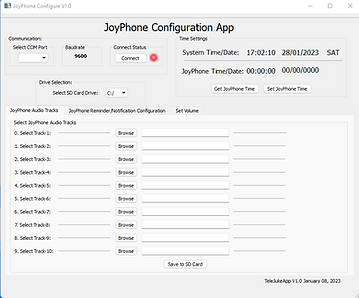
With the hardware assembly complete, the next step is to set up the necessary software. The especially created software aimed at simplifying the interface for a caretaker, can be found at the link provided here. Note that this application is compatible with Windows operating systems only.
The Arduino Nano is the beating heart of the JoyPhone and with the JoyPhone code we have created you will be able to upload the JoyPhone program on the Arduino Nano Controller. Once done, you will set the correct time to support the Reminder function and insert the SD card to store the audio files.
A full description how to install and operate the software can be found in the full manual. Also, have a look at the following videos which are also referred to in the manual.
Program the Arduino Microcontroller
Set the JoyPhone Date and Time
Upload Audio Files to SD Card
3D Printing the Enclosure
To protect your electronics, you have the choice to purchase an off the shelf enclosure, or 3D print the box that we have especially designed and made available to you. We recommend using PLA materials which will work well in Singapore tropical climate.

Operating the JoyPhone
With the hardware and software set up successfully, you are now ready to connect them together. You can use the JoyPhone to play audio files based on the dialed number on the rotary telephone or set reminders to ring and play a specific audio file. There is also a feature to adjust the volume of the handset. Have a look at the videos below.
Play Audio Files on the Telephone
Set Reminders
Set the Telephone Volume

_edited.jpg)